
The making of
a carbon wheelset.
Inside the complete production process
A carbon rim must hold a tire, support spoke loads and remain dimensionally accurate. Then it must become a wheel that stays true under use.
That is why manufacturing is not simply a sequence of cutting, molding and painting. It is a chain of structural decisions—and checks that prevent one stage from passing a problem to the next.
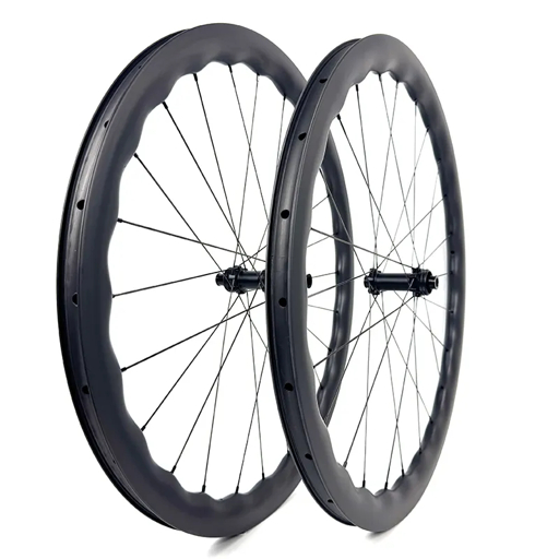
The whole production process of a carbon fiber wheelset connects two manufacturing jobs: making a dimensionally controlled composite rim, then assembling it with compatible hubs, spokes and nipples into a correctly tensioned wheel. Inspection links those jobs together.
This guide follows a representative prepreg, closed-mold route for modern carbon clincher and tubeless-ready rims. Tubular rims, filament-wound rims and other construction methods require different details. Procedures vary by manufacturer; the article does not describe XDRU’s proprietary factory process.
Before carbon is cut,
the wheel has to be defined.
A road rim is not simply a deep aerodynamic ring. Its tire bed must locate the tire correctly. Its spoke bed must support the nipple loads. Its walls must connect those regions into a continuous structure.
The drawing therefore needs to specify more than depth and width. It must resolve the bead-seat geometry, tire system, spoke-hole arrangement, valve opening, local reinforcement and relevant operating limits.
The wheel design also determines the hub, spoke count, lacing and intended use. A lightweight climbing build and a deeper aero build should not be treated as identical structures with different sidewall heights.
Production output / A controlled designTooling and layup follow the same revision.
The mold, cut patterns, layup instructions and inspection requirements must refer to the same product revision. Otherwise, individually correct operations can still produce the wrong combination.
Prototype development and product validation establish whether the design meets its declared use. The factory then needs a repeatable way to reproduce that design.
Material handling becomes
structural quality.
The factory receives a material system, not just “carbon.”
In a prepreg route, carbon reinforcement arrives already impregnated with resin. Fiber manufacture and prepreg manufacture are upstream processes; they are not normally performed on the wheel-building floor.
Incoming records identify the reinforcement, resin system, batch and handling requirements. Where cold storage is required, the supplier’s temperature and time limits govern the process.
Shelf life is not the same as out-life. One concerns storage under specified conditions; the other concerns permitted exposure outside those conditions. Material preparation must also control contamination and avoid introducing moisture during handling.
Cutting creates the rim’s reinforcement kit.
Templates or programmed cutters produce defined shapes. Their orientation matters: rotating a piece can change how its fibers carry load even if the piece still fits the mold.
A layup kit should identify the pieces, their sequence and their placement. Around a rim, overlaps and reinforcement zones are engineering details—not places to improvise when a sheet does not fit neatly.
Layup decides what happens
inside the familiar rim shape.
The operator follows the specified reinforcement schedule, placing fibers around the rim’s contours and the areas that need local support.
Those include structurally important regions such as the tire interface and spoke bed. The exact ply architecture is product-specific; there is no universal “correct number of carbon layers” for road rims.
Wrinkles, bridging and unintended gaps can prevent the laminate from matching the designed structure. Careful placement matters especially where the material must conform to tight curves.
In one common route, an internal bladder supports consolidation while the closed mold controls the outer shape. Other processes use different cores, mandrels or forming arrangements.
Conceptual tooling relationship
Curing is a controlled history.
Not a temperature on a display.
During cure, the resin system develops the structure that holds the reinforcement together. Consolidation and cure must follow the validated material-and-tooling process.
The relevant information includes the temperature ramp, dwell, pressure sequence and cooling conditions. Two cycles that reach the same peak temperature are not necessarily equivalent.
There is no universal cure temperature or bladder pressure for all carbon rims. Not every rim needs an autoclave, and an autoclave claim alone does not establish superior quality.
After the required release conditions are met, the rim is removed and temporary internal tooling is extracted as the design permits. Some material systems or processes include a specified post-cure.
The raw rim gets its first opportunity to fail inspection.
Before finishing adds cost or hides accessible surfaces, the manufacturer can check mass, gross geometry, surface condition and accessible internal features against the production specification.
A low mass is not automatically a success. A rim that is unexpectedly light or heavy may need investigation because mass is also a process-consistency indicator.
A beautiful surface cannot tell you
what happened inside the mold.
Machining and finishing must
respect the load paths.
Molding flash is removed and the rim’s specified features are completed. Depending on the design, that may include drilling spoke holes, valve openings and nipple-access holes.
These are not all the same feature. An opening in the tire bed used for nipple access serves a different purpose from the spoke hole and nipple seat carrying the spoke load.
Hole location, diameter and angle affect component fit and the path of the spoke into the rim. Machining quality, tool condition and edge condition therefore matter to more than appearance.
Drilled does not automatically mean defective.
Some manufacturers mold spoke or valve features; others drill specified features in a laminate designed for that operation. A molded-hole construction and a reinforced drilled-hole construction are different engineering routes.
Their merits must be judged as complete designs. It is misleading to declare every drilled carbon rim structurally compromised simply because machining cuts some fibers.
Finishing is not always sanding and painting.
Some rims receive surface preparation, coating and graphics. Others are designed to retain an as-molded finish with little or no sanding. Neither a glossy coating nor an exposed carbon texture proves structural quality.
Final rim inspection should focus on the specified tire interface, dimensions, hole features, condition and other release criteria—not just whether the decals are straight.
Now the rim becomes a wheel.
This is a second engineering job.
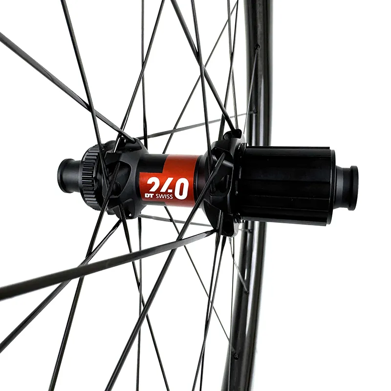
Before lacing, the rim must match the hub’s hole count, spoke arrangement and nipple system. The selected spokes must fit the intended hub and rim interfaces.
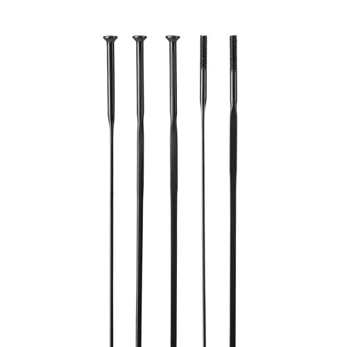
Spoke length depends on the rim’s effective rim diameter, hub geometry, lacing pattern and relevant component dimensions. Rim depth alone does not determine it.
Effective rim diameter concerns the spoke/nipple seating geometry used for the build calculation—not simply the visible outside diameter of the rim. Use the rim and nipple manufacturer’s definition rather than treating every quoted ERD as identical.
Hub preparation must also match the ordered axle, rotor and cassette configuration. A correctly built wheel with the wrong freehub is still an incorrect shipment.
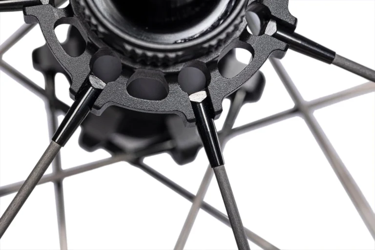
Lacing then connects the components in the specified pattern. Correct spoke placement, nipple engagement and approved thread preparation establish a sound starting point for tensioning.
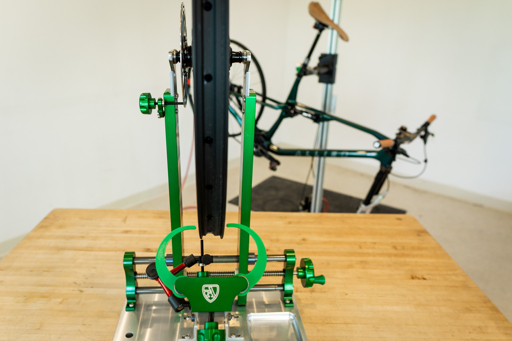
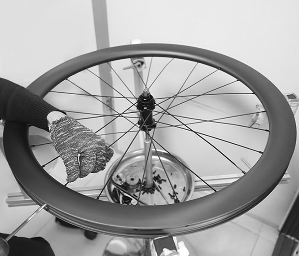
A truing stand sees alignment.
It does not certify the build.
A wheel can look straight while carrying an unsuitable tension distribution.
The builder must evaluate alignment, dish and spoke tension together, then check that the result remains stable after controlled settling.
Tension is adjusted.
Stability is earned.
Spoke tension is increased progressively while the builder controls three geometric outcomes: lateral alignment, radial alignment and dish.
The objective is not the highest possible tension. It is the appropriate target and distribution for that wheel, within the limits of the rim, spokes, nipples and hub.
A tension meter also needs the appropriate relationship between its reading and the spoke being measured. A raw instrument reading is not a universal tension value across every spoke profile or material.
Left and right sides may have different average tensions because their geometry differs. An instruction to make every spoke in the wheel equal can therefore be wrong. Consistency must be judged within the intended build, not against a simplistic rule.
Why the wheel is checked more than once
Controlled settling or de-stressing operations help seat components and reveal changes before shipment. The builder then rechecks tension and geometry, repeating the approved sequence as needed.
This wheel-building operation is not a heat-treatment process and should not be confused with curing the carbon rim. Its purpose is to stabilize the assembled wheel.
Inspection checks this wheel.
Validation checks the design.
Routine inspection asks whether an individual product meets its specification. Validation asks whether the design is suitable for the declared use. Neither replaces the other.
A factory cannot test every saleable wheel to destruction. Product-development tests and any production sampling must therefore be distinguished from routine release checks.
| Layer | Examples of evidence | Question answered |
|---|---|---|
| Process control | Material batch, handling record, layup revision and cure history. | Was the approved manufacturing route followed? |
| Rim release | Specified dimensions, mass, interface condition and feature checks. | Is the rim acceptable for the next production stage? |
| Wheel release | Correct build, stabilized tension, alignment, dish and hub configuration. | Does this assembled wheel meet its release requirements? |
| Design validation | Relevant fatigue, impact, tire-interface and other use-specific evaluations. | Does the product design support the intended application? |
These are inspection categories, not a claim that every manufacturer performs every listed method. Test selection, acceptance criteria and sampling frequency are product-specific. Rim-brake designs also require evaluation of their braking and thermal requirements.
The last production operation is a correct handover.
Before packing, the manufacturer confirms the ordered configuration, supplied accessories and product identification. Where tape and valves are installed, their condition and any specified sealing check belong to that build’s release process.
Tubeless-ready does not mean ready to inflate with any tire. The installer still needs the approved tire, correct installation and applicable pressure instructions. Packaging should protect the wheel, and the supplied information should explain what remains to be done.
The finished specification is visible.
The discipline behind it is not.
Product context / Not a factory-process claim
What a production chain becomes
on a wheelset specification.
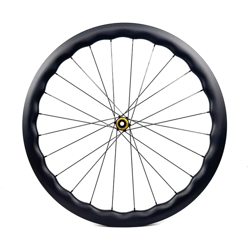
XDRU / CHASE 45 AERO SL
A complete build,
not just a carbon label.
The CHASE 45 AERO SL carbon road wheelset listing specifies a 45 mm rim depth, 22 mm internal width, Toray T800 + T700 construction, 24/24 spoke holes and a 36T ratchet hub.
Those details connect to separate production decisions: tooling geometry, laminate specification, hole layout, component matching and final assembly.
Manufacturer-listed specifications are not independent verification of layup details, cure settings, inspection frequency or test results. Confirm the current build before ordering.
The useful buying question is not simply “Which carbon grade does it use?” It is whether the manufacturer can connect its product claims to a defined build, appropriate validation and repeatable production.
That connection is traceability: knowing what was specified, what was used, what was checked and why the finished wheel was accepted.
Questions worth asking
Carbon wheelset production
Why can two carbon rims with the same shape perform differently?
The outer geometry does not disclose the resin system, reinforcement placement, consolidation or manufacturing consistency. Identical-looking profiles can therefore represent different composite structures.
Are molded spoke holes always better than drilled holes?
They are different design routes. Molded features can preserve fiber continuity around an opening, while a drilled design must account for machining and local load support. Compare the validated complete structures, not the hole-making method in isolation.
Does every carbon rim require an autoclave?
No. Composite materials support different manufacturing routes. Suitability depends on the material system, tooling and validated process, not the presence of one particular machine.
Why does a wheel need stabilization after tensioning?
Seating and assembly movement can change tension and alignment. Controlled stabilization followed by reinspection helps identify those changes before the wheel is released.
Should all spokes have identical tension?
Not necessarily. The two sides can require different average tensions because of wheel geometry. The build must meet its specified distribution and component limits.
Can a wheel be straight but poorly built?
Yes. Alignment alone does not establish suitable tension, correct component engagement or stability after settling. Those require separate checks.
Does a low finished weight prove better manufacturing?
No. Weight is one specification and can also be a consistency indicator. A lighter result is only useful if the finished design still meets its required structural, compatibility and operating criteria.