
Wheel engineering / Contact geometry / Build durability
A wheel can be straight, correctly dished and apparently well tensioned—and still contain a poor mechanical fit at every spoke elbow.
Spoke holes, spoke heads and flange edges form a small but highly loaded interface. Their geometry determines how a spoke seats, how its load enters the hub, and whether repeated changes in tension produce manageable elastic movement or damaging local bending. These details deserve attention before the first nipple is tightened.
This discussion focuses primarily on conventional J-bend steel spokes in metal hub flanges. Straight-pull systems follow the same general need for a supported, compatible load path, but their head seats and retention features require separate assessment. Rim spoke holes and nipple seats matter too, but they are a different interface.
01 / The load path begins before the spoke shaft
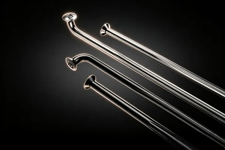
In a tensioned wheel, each spoke pulls between the rim and hub. At a J-bend hub, the head retains the spoke while contact around the bend transfers load into the flange. The interface is not simply a straight rod pulling on a flat washer: the spoke changes direction, and that bend makes support geometry important.
During riding, spoke tension changes as the wheel carries load, corners, brakes and transmits drive torque. Repeated tension changes are normal. Problems arise when an unsuitable seat, excessive clearance or a poorly supported elbow adds local bending and movement at a fatigue-sensitive location.
A broken elbow is therefore not automatically evidence of an inadequate spoke diameter. It can also be evidence that the spoke and flange were poorly matched, incompletely seated, or operating in a wheel with unsuitable tension.
02 / Spoke-hole diameter: clearance without careless looseness
The hole must allow the intended spoke to pass through during assembly. That includes the threaded end and, where relevant, the spoke’s shaped section. A hole that is too small can prevent installation or tempt the builder into forcing a component through.
Excessive clearance creates a different concern. Combined with an unsuitable bend length or flange thickness, it can leave the elbow poorly supported and change where the spoke bears against the flange.
There is no universal ideal hole diameter for every spoke. The relevant dimensions include the spoke diameter at the elbow, thread clearance, bend shape, head geometry and flange profile. A nominal spoke size is not a complete compatibility specification.
Installation becomes a warning
If a compatible-looking spoke requires significant force, stop. Check the hole, thread diameter, spoke shape and intended installation method. Do not treat a forced fit as evidence of better support.
Support becomes the question
A spoke passing easily through a hole does not prove the combination is suitable. Check where the head seats and whether the elbow remains unnecessarily unsupported after controlled tensioning.
03 / Flange thickness and bend length must agree
Flange thickness determines how much material occupies the space between the spoke head and the bend. Bend length determines how that space is accommodated. Neither dimension is useful in isolation.
If the bend is too long for the flange geometry, the elbow can stand away from the supporting surface. As tension rises, the spoke may be pulled into a new shape instead of settling into a well-supported seat.
If the bend is too short, the spoke may not seat naturally through the flange. Forcing it into position can produce an unsuitable contact pattern or interfere with the intended spoke line.
A spoke that rattles slightly in an untensioned hub is not, by itself, a failure. The useful assessment concerns the specified component pairing and the contact geometry that develops under tension.
Why the head cannot be assessed alone
A head can appear neatly seated while the elbow is still poorly supported on the opposite side. Conversely, visible clearance under part of a head does not tell the whole story without knowing the intended seat geometry.
Inspect the assembly as a three-dimensional contact system: head seat, hole wall, bend support and outgoing spoke line. One attractive-looking contact surface does not validate all the others.
04 / Flange edges define how contact develops
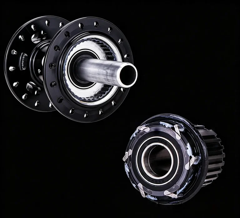
The edge around a spoke hole is not just a finishing detail. A sharp burr can concentrate contact and mark the spoke during assembly. A suitable chamfer or radius can remove that abrupt transition and help the head or elbow seat as intended.
However, a larger chamfer is not automatically better. Removing more material also changes the supporting section around the hole. A deep countersink that does not match the spoke can reduce useful support instead of improving it.
The appropriate edge treatment depends on flange material, thickness, hole layout and the intended spoke. The goal is a deliberate bearing surface—not the biggest possible bevel.
The outer flange edge matters too
Material between a spoke hole and the flange’s outer edge forms part of the load-bearing structure. Hole size, spacing and edge distance therefore belong in the same design discussion. Enlarging a hole removes material from that structure.
Do not drill, aggressively countersink or reshape a finished hub to make an unsuitable spoke fit unless the component manufacturer explicitly authorizes that modification. A wheelbuilder’s job is to select a compatible assembly, not redesign the flange with a hand tool.
05 / Washers solve a specific fit problem—not every problem
A purpose-made spoke-head washer can add effective thickness beneath the head. In a suitable application, that can reduce excess clearance associated with a relatively long bend and help bring the elbow into better support.
That does not make washers a universal upgrade. A washer changes the head position and contact geometry. It must suit the spoke, flange, available clearance and component instructions.
| Observed condition | Useful response | What a washer cannot do |
|---|---|---|
| Excess bend clearance on an otherwise compatible assembly | Assess whether an approved spoke-head washer improves seating. | Guarantee compatibility without checking the resulting contact. |
| Spoke will not pass through the hole | Verify the intended spoke specification and installation method. | Create missing hole clearance. |
| Cracked or severely damaged flange | Remove the hub from service and assess replacement. | Restore the flange’s structural integrity. |
| Spoke head and elbow already seat correctly | Follow the specified assembly without adding unnecessary parts. | Provide an automatic improvement merely by being present. |
A spoke-head washer at the hub is also different from a nipple washer at the rim. They occupy different locations, support different components and should not be treated as interchangeable accessories.
06 / Lacing changes the direction of loading
The spoke does not leave the flange in one universal direction. Cross count, flange diameter, rim diameter and left-to-right wheel geometry influence its outgoing line. The elbow must accommodate that line without an unnecessary local kink.
With crossed lacing, the spoke has a tangential component that allows the wheel to transmit torque. Bracing angle—the lateral angle between spoke and wheel center plane—is a separate dimension. It should not be confused with how tangentially a spoke leaves the flange.
Head orientation also changes which side of the flange carries the outgoing shaft. Neither heads-in nor heads-out is universally superior. Use an approved lacing pattern, respect clearance requirements and assess the actual spoke path.
07 / Tension and stress relief cannot rescue bad geometry
Correct component fit is the starting point. The build still needs suitable tension, controlled seating, removal of spoke wind-up and an appropriate stress-relief process. These are related tasks, but they are not identical.
Establish the intended contact
Heads, elbows and nipples settle into their working positions as the build progresses. Controlled bedding helps reveal changes before the wheel enters service.
Address localized residual stress
Controlled temporary loading is used in established building methods to improve the condition of highly stressed spoke regions. It is not permission to crush, kink or arbitrarily overload a wheel.
After these operations, recheck trueness, dish and tension. A wheel that remains straight but develops isolated low-tension spokes has not passed a complete verification.
Tension should follow the limits of the actual components. More tension is not a substitute for better fit, and there is no single correct tension for every rim, hub and spoke combination. Compare uniformity within each side of a dished wheel; equal left- and right-side tension is not normally the target.
08 / Read the marks before reusing a hub
A used aluminum flange may show witness marks where steel spokes previously seated. Such marks are not automatically evidence of failure. Their depth, shape and relationship to the surrounding material matter.
Clean the flange and inspect both faces of every hole. Look for cracks, pronounced elongation, deep cutting, displaced material and damage reaching toward the outer edge. Do not hide questionable features beneath new spokes or washers.
Existing spoke seats may also reflect the previous lacing direction. When rebuilding, consider those contact marks alongside the hub’s permitted patterns. Do not use an incompatible pattern simply to follow an old indentation, and do not aggressively file away evidence to make the flange look new.
09 / A practical inspection and build sequence
- Confirm the intended interface: spoke type, elbow diameter, bend geometry, head style, spoke count and permitted lacing pattern.
- Inspect each flange face and hole under good lighting. Separate harmless surface marks from burrs, deformation and crack-like features.
- Trial-fit representative spokes in the orientations the build will use. Check installation clearance and the relationship between head, bend and flange.
- Verify spoke-length inputs, including pitch-circle diameter, center-to-flange distances, rim dimensions and lacing pattern.
- Increase tension progressively. Watch how the elbows seat and whether the outgoing shafts develop avoidable local bends.
- Use only appropriate, permitted washers or other interface parts. Recheck their effect rather than assuming the added part solves the problem.
- Complete controlled seating, wind-up removal and stress relief using a method suitable for the wheel.
- Verify final trueness, dish and side-specific tension consistency. Investigate unexplained changes instead of merely correcting the rim position again.
10 / Straight-pull does not mean interface-free
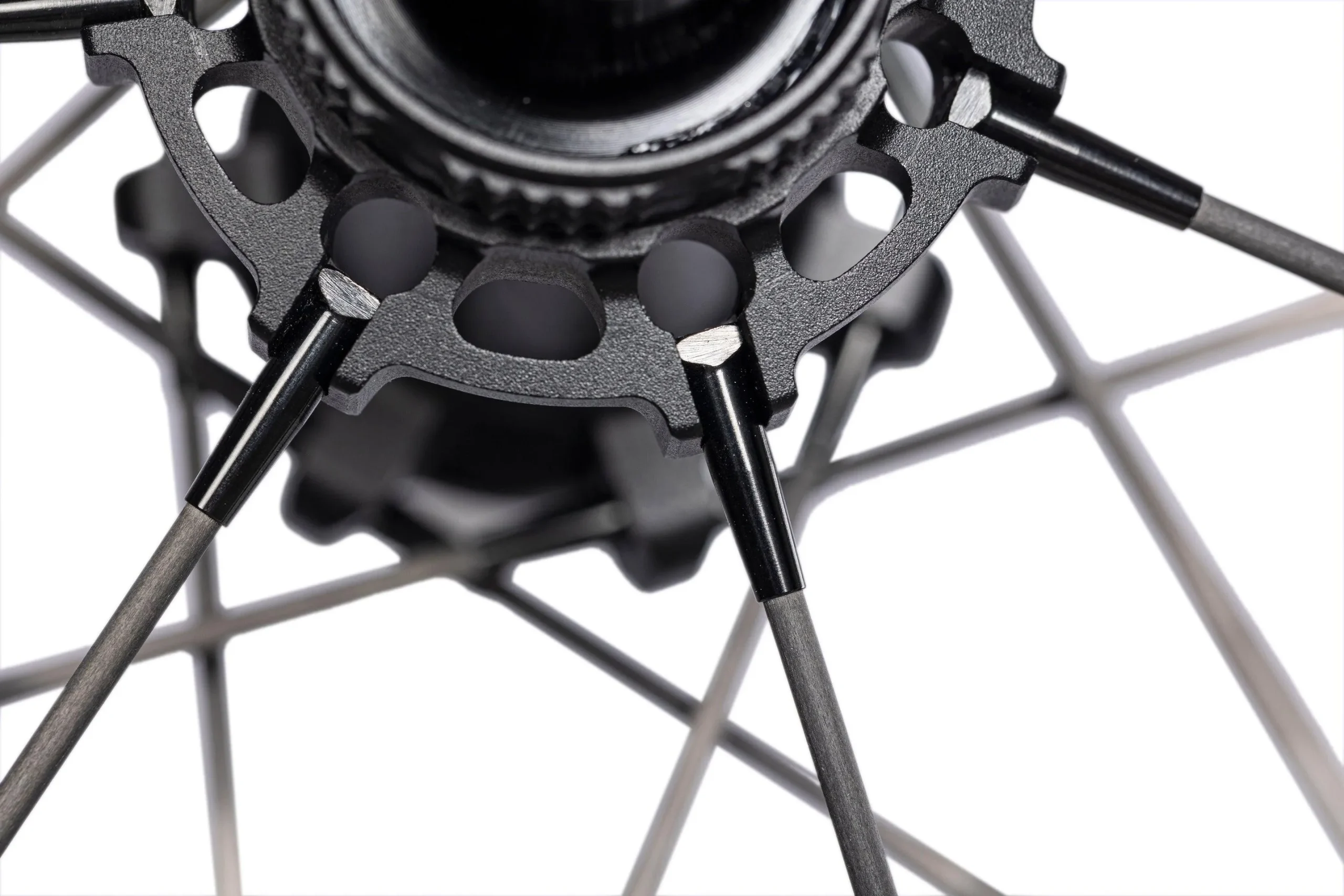
Straight-pull spokes remove the conventional J-bend, but they still need a correctly supported head. Their seats, slots, retention features and outgoing alignment remain important.
A spoke that looks similar may have a different head shape or retention requirement. Treat straight-pull components as a specified system rather than assuming that matching length and shaft diameter establishes compatibility.
The relevant question is not whether one format eliminates every possible failure. It is whether the complete interface supports the spoke reliably throughout the wheel’s operating loads.
Build the contact correctly, not just the wheel straight
Spoke holes set clearance. Heads provide retention and seating. Elbows need appropriate support. Flange edges shape contact while preserving the material that carries the load.
The decisive principle is compatibility: matching these details before tensioning, then verifying that the intended fit survives seating and final adjustment. A truing stand reveals rim movement; it does not, by itself, certify the quality of every spoke-to-hub connection.