
Build it right.
Check it twice.
How to install carbon wheels—from tire and tubeless setup to cassette installation, disc brake rotors and the final on-bike safety inspection.
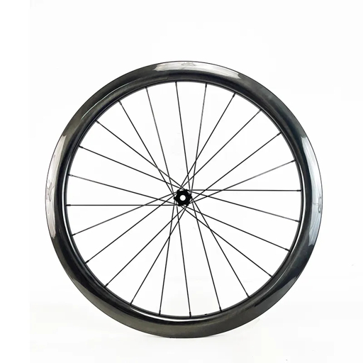
Standards and tools
Tape, valve and tire
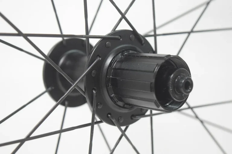
Cassette and spacers
Rotor and fasteners
Bike fit and test ride
The scope—and the safety boundary.
This guide focuses on conventional spoked, disc-brake carbon wheels with clincher or tubeless tires. Tubular gluing, structural carbon repairs, hydraulic brake bleeding and hub rebuilding need separate procedures. Component manuals take precedence over general instructions. If compatibility, torque or brake operation remains uncertain, stop and use a qualified bicycle mechanic.
Compatibility
Do the compatibility work before picking up a tool.
A carbon wheelset can share the same nominal diameter as your old wheels and still be incompatible with the bicycle. Confirm the exact interfaces before transferring tires, cassettes or rotors.
Wheel and axle standards
Match bead-seat diameter, front/rear hub spacing, axle diameter and approved end caps. Use the correct axle for the frame or fork, including its length and thread pitch. Do not force an axle or improvise an end-cap conversion.
Tire and rim system
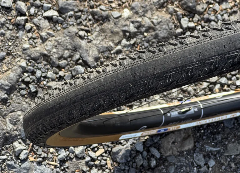
Confirm tire diameter, permitted width, hooked or hookless bead design, tube/tubeless approval and pressure limits. A matching diameter alone does not prove safe tire fit.
Cassette and freehub
Identify the exact cassette model and required freehub: HG, XD, XDR, Micro Spline or another specified interface. Speed count alone is not enough. Establish the spacer requirement from the actual combination.
Rotor and brake system
Match Center Lock or six-bolt mounting, rotor diameter, rotor thickness, pad compatibility and frame/fork approval. A larger rotor is not a drop-in upgrade without the correct approved brake arrangement.
Suitable torque wrench or wrenches; correct cassette and rotor tools; relevant hex/Torx bits; approved tire levers; pump with pressure gauge; compatible tape, valve and sealant if needed; manufacturer-specified lubricants; clean lint-free cloths; suitable brake cleaner; safety glasses and clean gloves.
A chain whip is generally needed when removing a conventional cassette, not for tightening its lockring during installation. Keep grease and sealant work separate from clean brake surfaces.
Wheel inspection
Inspect the wheel before covering it with a tire.
Remove packaging and inspect the rim, bead seats, valve hole, hubs and spokes. Look for shipping damage, cracks, loose components, damaged threads or sharp edges that could damage tape or a tire.
Confirm that the correct end caps are present and fully seated. Check for obvious bearing roughness or play. Do not sand, drill or “clean up” a carbon rim defect at home; ask the supplier to assess it.
Inspect pre-installed rim tape rather than assuming it is ready. Packaging tape or a basic rim strip is not necessarily a pressure-rated tubeless seal.
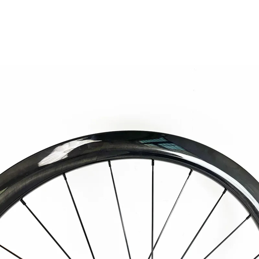
Protect the parts you are about to fit.
Do not clamp the carbon rim in a vise or support a wheel on a brake rotor. Keep rotors off dirty benches and away from aerosol lubricant.
If the old wheel is out of the bicycle, insert the appropriate pad spacer into the hydraulic caliper. Do not squeeze the brake lever with neither a rotor nor the specified spacer fitted.
Tape and valve
Build an airtight rim bed—not a thicker one.
Tubeless rim tape must match the rim profile and cover the required rim-bed area without interfering with the bead seats. Follow the wheel manufacturer’s specified width, number of layers, overlap and installation method.
Internal rim width is not automatically the correct tape width: the tape follows a shaped channel rather than a flat line. Conversely, adding layers at random can make mounting harder or change the fit.
- Clean and dry the rim bed using a cleaner approved for the rim and tape adhesive.
- Apply the specified tape smoothly, with the required tension and overlap. Avoid wrinkles, trapped contamination and uncovered spoke holes.
- Make the valve opening using the tape/valve manufacturer’s method. Do not cut a large slit that can spread into a leak.
- Install a compatible valve base and a stem long enough for the rim depth and pump head. Tighten its retaining nut as specified—usually by hand, not by crushing it with pliers.
Some sealed rim designs do not require conventional tape. Others need a specific tape system. Do not add or remove tape simply because another wheel uses a different arrangement.
Tire installation
Mount the tire with technique, not brute force.
For a tubeless setup
- Confirm the exact tire is approved for the rim. Check its condition and rotation arrow before mounting.
- Fit the first bead. Keep the bead in the rim’s center channel to create slack as you work around the wheel.
- Fit the second bead using the manufacturer’s recommended sequence. Keep already-mounted sections in the center channel, and ensure the valve base is correctly positioned between the beads.
- Use only approved tire levers if needed. Avoid metal screwdrivers and do not damage the bead, rim or tape. If force becomes excessive, stop and recheck the technique and compatibility.
- Add the specified type and quantity of sealant using an approved method: before closing the final bead or through a compatible valve after seating.
- Inflate using an appropriate pump or controlled inflator. If required, approved assembly fluid and temporary valve-core removal can help airflow and seating.
- Check the molded bead-reference line on both sides around the entire wheel. It should sit consistently relative to the rim. Audible pops alone do not prove correct seating.
- Refit the core if removed, set the intended riding pressure and distribute sealant according to its instructions. Check for leaks and pressure retention before riding.
For a tube-type setup
Use a compatible tire, tube and rim protection. Lightly inflate the tube so it holds shape, install it without twists and mount the tire without trapping the tube beneath a bead. Check both sides before gradually inflating and verifying even seating.
Follow any tube-material restrictions, particularly for TPU, latex or rim-brake applications. A tube does not make an otherwise incompatible tire-and-rim combination acceptable.
Never exceed a limit to make the bead seat.
Respect the lowest applicable mounting and operating pressure limits from the wheel, tire and other relevant components. A compressor reservoir’s rating is not the tire’s permissible pressure. If the bead will not seat within the allowed range, deflate and diagnose the fit.
For road hookless systems, do not assume the tire’s printed maximum is allowed. Schwalbe cites a 5 bar ceiling and lower width-specific limits for wider tires; wheel manufacturers may impose further restrictions. Use the exact approved combination and its limits, not a generic target.
Leaks at spoke holes are not a cue to tighten nipples.
Air escaping near nipples or a rim vent can indicate that pressure has entered the rim cavity through a tape or valve leak. Deflate and inspect the sealing system. Never plug a designed rim vent or keep adding pressure to overcome the leak. Suspected structural damage needs manufacturer assessment.
Cassette fit
Install the cassette with the correct body and spacer stack.
Most modern performance wheelsets use a cassette on a freehub, not a screw-on freewheel. The exact cassette/freehub interface determines the fitting method.
HG-style splined cassettes
- Check the cassette manual for the required body and any behind-cassette spacer.
- Clean the interface and apply lubricant only where and as specified by the hub/cassette manufacturer.
- Align the keyed spline and slide the cassette or individual sprockets into place. Preserve the specified sprocket and spacer order.
- Start the lockring squarely by hand where the design allows. If it binds immediately, stop rather than forcing the threads.
- Fully engage the correct tool and tighten to the cassette manufacturer’s specified torque.
XD and XDR cassettes
Follow the cassette’s dedicated procedure rather than treating it as an HG lockring assembly. SRAM specifies greased driver threads, proper seating, full tool engagement and a suitable guide-pin tool for its XDR installation.
SRAM XD cassettes can fit an XDR driver with the specified 1.85mm spacer. SRAM XDR cassettes require an XDR body. Do not install that spacer indiscriminately on every XDR setup.
After tightening
Check that the sprocket assembly is secure with no unexplained lateral looseness. If it moves, inspect compatibility, seating, spacer requirements and lockring engagement. Do not exceed torque or add random washers to remove play.
There is no
“carbon wheel torque.”
Cassette lockrings, rotor lockrings, rotor bolts, caliper bolts and axles have different specifications. Use the correct manual for each fastener and its prescribed lubrication or threadlocker condition.
For example, SRAM’s cited Road AXS XDR cassette procedure specifies 40 N·m. That is a component-specific value—not permission to apply 40 N·m to unrelated parts.
Rotor installation
Keep the braking surface clean. Match the mounting system.
Handle a rotor by its carrier or non-braking areas with clean hands or gloves. Keep grease, chain lubricant and sealant away from the braking track and pads. If cleaning is needed, use the brake manufacturer’s approved cleaner.
Center Lock rotor installation
- Confirm rotor diameter, thickness, pad compatibility and hub fit.
- Install the rotor in its marked direction of rotation and prescribed orientation.
- Use the correct lockring for the hub, axle/end-cap clearance and rotor. Internal- and external-spline lockrings can require different tools.
- Start the lockring without cross-threading, fully engage the correct tool and tighten to its specified torque.
Six-bolt rotor installation
- Confirm the rotor’s direction and that the mounting faces are clean.
- Use the specified bolts, washers or retention hardware. Follow instructions on bolt replacement and factory-applied threadlocker.
- Start all bolts, then tighten incrementally in the prescribed alternating pattern.
- Finish each bolt at the rotor manufacturer’s specified torque. Do not add grease or threadlocker unless instructed.
Do not assume every six-bolt rotor uses the same torque, or that every Center Lock lockring is interchangeable. An approved rotor adapter is a separate compatibility decision.
On-bike fit
Seat the wheel correctly before adjusting anything else.
- Prepare the rear derailleur according to its manufacturer’s wheel-removal procedure. For many conventional drivetrains, selecting the smallest rear sprocket helps; systems with cage modes may require a different sequence.
- Remove the pad spacer only when ready to guide the rotor between the pads. Do not force the rotor against them.
- Locate the hub fully in the dropouts, with all correct end caps installed. Guide the chain onto the intended sprocket.
- Insert the correct axle and engage it by hand. If the thread will not start easily, stop and recheck alignment and axle compatibility.
- Lubricate and tighten the axle according to the frame/fork and axle instructions. Quick-release systems require their own clamping procedure, not a substituted thru-axle method.
- Check that the wheel is centered as intended and that it remains secure. Never loosen an axle to eliminate brake rub.
Now check tire clearance.
Measure the actual installed tire at the intended pressure. Check the fork crown and legs, chainstays, seatstays, seat tube and any fenders. Follow the bicycle manufacturer’s minimum clearance requirements, allowing for wheel/tire movement and relevant mud or debris.
A tire that just clears in a repair stand is not automatically safe under load. Do not solve rubbing by leaving the wheel off-center or under-tightened.
Settle the brakes before the first ride.
Once the rotor is installed, gently operate the brake levers to restore normal pad contact. Check for a firm, repeatable lever feel, then spin the wheel. If it rubs, first verify wheel seating, axle security and rotor fit before considering caliper alignment.
Persistent rubbing, a soft lever, leakage, loose hardware or poor braking requires correction before riding. Caliper adjustment must follow the brake’s procedure and torque requirements; use a mechanic if unsure.
Drivetrain check
Do not assume the old shifting adjustment will transfer perfectly.
Different hubs can place a cassette slightly differently. With the bicycle securely supported, turn the cranks slowly and check shifting across the usable range. Keep fingers, clothing and tools clear of the moving drivetrain.
Confirm that the chain does not move beyond the smallest or largest sprocket and that the derailleur clears the spokes. If it looks unsafe, stop the test rather than shifting repeatedly toward the spokes.
Recheck cassette security and wheel seating before changing derailleur settings. Indexing, limit screws, chain gap and hanger alignment are different adjustments; one should not be used to conceal a fault in another.
If the new cassette changes sprocket range or drivetrain type, verify derailleur capacity, maximum sprocket, chain compatibility and chain length. A cassette that physically fits the freehub may still be incompatible with the drivetrain.
Static checks
The pre-ride checklist: every item needs a clear pass.
- Axles are correctly engaged and secured to the specified procedure.
- Both wheels sit correctly, with no unexplained hub play.
- Tire beads are evenly seated around both sides of each wheel.
- Pressure is appropriate for the load and below every applicable limit.
- Tubeless valves, tape and tires show no unresolved leaks.
- Cassette is secure, with the required spacers and no loose sprockets.
- Rotors and retention hardware are correct, secure and clean.
- Brake levers feel normal and both brakes function.
- Wheels rotate without significant drag, contact or unexplained wobble.
- Tire clearance meets the bicycle manufacturer’s requirements.
- Shifting is controlled, and chain and derailleur clear the spokes.
- No tool, packaging piece, pad spacer or loose accessory remains in the assembly.
First ride
A short shakedown comes before a fast ride.
Begin in a flat, clear, traffic-free area. At walking or low speed, confirm that each brake controls the bicycle predictably. Then make a short, gentle ride to check shifting, steering, unusual noises and tire behavior.
New pads and rotors need the brake manufacturer’s bedding-in procedure before normal hard use. Bed-in builds an even transfer layer on the rotor; it is not the same thing as simply dragging the brakes down a hill.
As one manufacturer-specific example, SRAM’s cited Road AXS procedure calls for approximately 20 controlled slowdowns from moderate speed to walking speed, followed by approximately 10 from a faster speed, then cooling. Remain seated and do not lock the wheels. Follow your own brake system’s procedure; have a mechanic do this if you are unfamiliar with its braking power.
After the shakedown, recheck wheel security, tire seating, pressure retention, clearance, cassette security and brake behavior. Inspect after cooling before handling rotors. Do not “give everything another turn”; verify fasteners by the correct torque procedure rather than adding extra tightness.
Common installation problems—and the first useful check.
| Symptom | Check first | Do not do this |
|---|---|---|
| Tire will not mount | Approved fit, bead in center channel, tape build and mounting method | Use a screwdriver or force a damaged bead over the rim |
| Bead will not seat | Compatibility, even positioning, valve airflow and approved assembly fluid | Exceed pressure limits to force a pop |
| Air escapes at nipples or a vent | Deflate; inspect tape, valve and rim condition | Plug the rim vent or tighten spoke nipples as a sealing fix |
| Cassette remains loose | Correct body, spacer stack, seating and thread engagement | Add arbitrary washers or exceed torque |
| Rotor rub after wheel installation | Wheel seating, end caps, axle security, rotor fit and alignment | Loosen the axle to move the rotor away from the pad |
| Shifting changed after wheel swap | Cassette security and position, wheel seating and drivetrain compatibility | Turn limit screws randomly |
| Soft lever or poor braking | Stop; assess brake condition, contamination and required service | Ride faster to see whether it improves |
| Tire contacts the frame | Measured mounted width, wheel centering and required clearance | Leave the axle loose or the wheel misaligned |
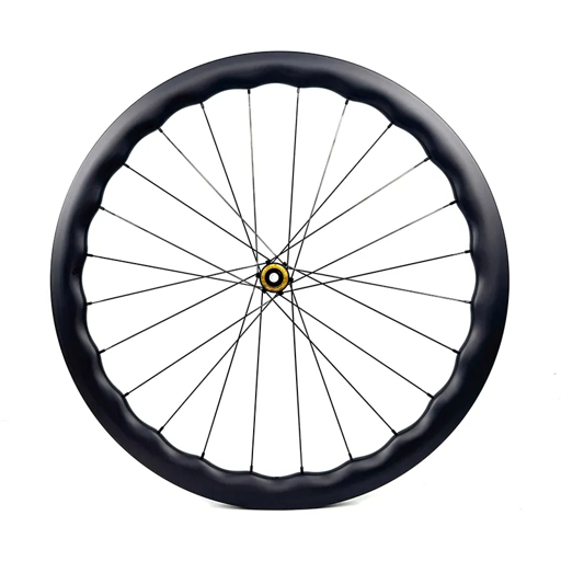
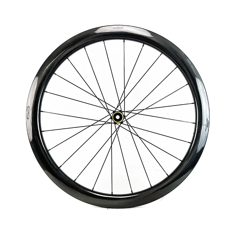
XDRU CHASE 45 AERO SL
The published configuration lists a 45mm tubeless-ready rim, 22mm internal width, Centerlock disc mounting, 12 × 100mm front and 12 × 142mm rear axles, and HG/XDR freehub options.
Those details start the fit check. Before assembly, also obtain the exact supplied freehub, bead design, approved tires, tape/valve requirements, pressure limits and component-specific installation instructions.
Check CHASE 45 AERO SL specifications →The questions worth resolving before you ride.
Can I reuse my old cassette and rotors?
Often, if they are compatible, within wear limits and in serviceable condition. Check the new freehub, required spacers, rotor mounting, diameter and thickness. Transfer does not mean no adjustment is needed.
Do new carbon wheels need spoke tightening?
Do not tighten spokes as a routine installation step unless the wheel manufacturer instructs it. A correctly supplied wheel should already be built and tensioned. Report loose spokes, significant runout or suspected build issues.
How much tubeless sealant should I use?
Follow the sealant and tire instructions for the actual tire size and system. There is no universal dose for road, gravel and MTB. Check compatibility and replenishment intervals as well as initial quantity.
Should I inflate to maximum pressure overnight?
Not as a blanket rule. Use only an approved seating and sealing procedure within all limits. Set riding pressure for the actual load, tire and conditions—not the maximum printed number.
Is carbon assembly paste needed because the rim is carbon?
No. Do not apply friction paste, grease or adhesive to the bead seat, rim bed or other interfaces unless the relevant manufacturer specifically requires it. Each interface has its own instructions.
The installation is finished
when the whole bicycle passes.
An inflated tire, a tightened cassette and a mounted rotor are intermediate results. Correct fit, secure interfaces, clean braking, safe clearance and a controlled test ride complete the job.
Resolve uncertainty on the workbench. Do not take it into the first descent.